Sika Waterbar® - Elastomer Clamped Type
Sika Elastomer Clamped Waterbars synthetic rubber based for use in steel clamping construtions
Sika Elastomer Clamped Waterbars are permanently elastic waterbars for sealing expansion joints made of synthetic rubber for use in connection with clamping structures made of steel. Sika Elastomer Clamped Waterbars are available in different shapes and sizes. Depending on the profile type, the clamped waterbars have one or two clamping legs for use as a single or double-sided clamped waterbar. Clamped waterbars for one-sided clamping are equipped with an internal or external cast-in leg.
- High tensile strength and elongation
- High permanent elasticity with high resilience
- Suitable for high levels of hydrostatic pressure
- Resistant to naturally occurring materials aggressive to concrete
- Resistant to a broad spectrum of chemical agents (specific testing is always recommended for each situation and exposure level)
- Dimensionally stable in contact with hot bitumen
- Robust cross-sections for handling on site
- Butt joints can be made by vulcanization on site
Overview
Usage
PRINCIPLES FOR USE- Design and installation in accordance with German Standards DIN 18197 and DIN 18533-1
- Jointing technology according to DIN 18197 and DIN 7865
- Vulcanizing of butt joints only by Sika trained and certified people and in accordance with
- Installation of clamping constructions only by Sika trained and certified people
Advantages
- High tensile strength and elongation
- High permanent elasticity with high resilience
- Suitable for high levels of hydrostatic pressure
- Resistant to naturally occurring materials aggressive to concrete
- Resistant to a broad spectrum of chemical agents (specific testing is always recommended for each situation and exposure level)
- Dimensionally stable in contact with hot bitumen
- Robust cross-sections for handling on site
- Butt joints can be made by vulcanization on site
Packaging
- Supplied as standard rolls of 20, 25 or 40 m dependent on profile, on Euro or disposable pallets
- Prefabricated formpieces, on Euro or disposable pallets dependent on size
- Accessories are supplied in a clamping set, as shown on the accessory list, packed on Euro pallets
Colour
Black
Product Details
CERTIFICATES AND TEST REPORTS
- DIN 18197, as relevant
- DIN 7865-2
- DIN 7865-4, as relevant
- DIN 18533-1, as relevant
- ZTV-ING, RiZ-ING, RiZ-ING Fug 6 for joint covers
- DB AG DS 804.6101
- Sika vulcanizing instructions
- Sika instructions for vulcanizing machines
- Sika Elastomer Clamped Waterbars installation Method Statement
Composition
Styrene-butadiene-rubber (SBR)
Shelf life
The product does not decompose if stored correctly
Storage conditions
Stored on the pallets as supplied on a flat base
- For long term storage > 6 months in enclosed areas: The recommendations of DIN 7716 apply. The storage area should be covered, cool, dry, free from dust and moderately ventilated. The Elastomer waterbars must be protected from heat sources and strong artificial lights with an high UV content
- Short term storage > 6 weeks and < 6 months in enclosed areas: The principles of DIN 7716 apply. On construction sites, outdoors: In dry storage, protected by suitable covers from direct sunlight, snow and ice, or any other form of contamination. Store separate from other potentially harmful materials, plant and equipment such as structural steel, reinforcements, fuels etc. Store away from traffic and site roads
- Short term storage < 6 weeks on construction sites, outdoors: Protected from contamination or damage. Protected by suitable covers from strong sunlight, snow or ice etc.
- Vulcanizing materials should be covered and stored in a cool, dry area free from dust and contamination. It is recommended that the stock requirements be coordinated for a maximum storage period of about 6 weeks.
System structure
The limits of water pressure and stress given in the tables below apply to standard uses with joint widths wnom of 20 mm or 30 mm, without any specific additional testing being required. Different values may be used when more precise information on all of the relevant stresses and structural requirements of the specific project is available. These systems are normally designed to be clamped on the side of the structure away from the water wherever possible.
Forms:
|
|
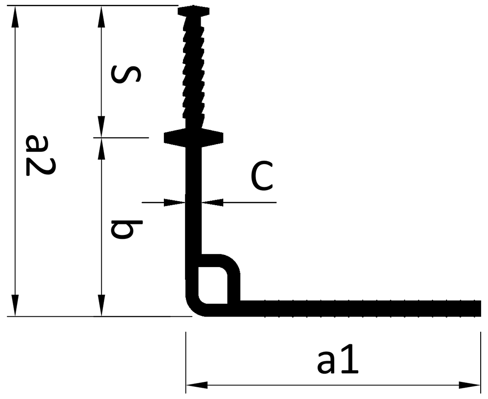
| Total width a1/a2 (mm) | Width b (mm) | Width c (mm) | Width s (mm) | Water pressure P (bar) | Resulting movement Vr (mm) |
| FM 350 K | |||||
| 190/200 | 115 | 10 | 85 | 1,5 | 20 |
| FM 500 K | |||||
| 225/272 | 172 | 13 | 100 | 2,0 2) | 20 |
| Total width a (mm) | Width b (mm) | Width c (mm) | Width s (mm) | Water pressure P (bar) | Resulting movement Vr (mm) |
| FM 350 KF | |||||
| 350 | --- 1) | 12 | 85 | 1,5 | 20 |
| F 300 KF | |||||
| 300 | --- 1) | 8 | 100 | 1,5 | 3 2) |
| FMG 350 | |||||
| 350 | --- 1) | 12 | --- | 1,5 3) | 20 |
|
|
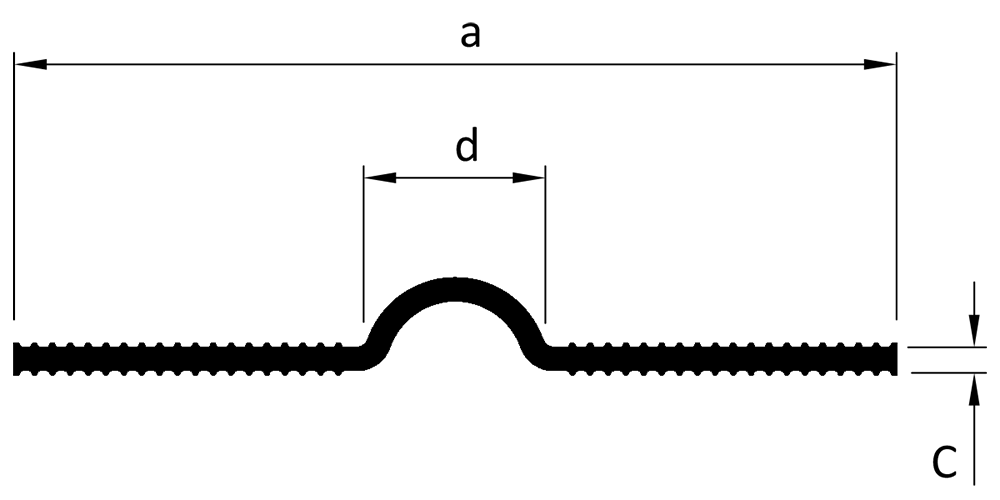
| Total width a (mm) | Width b (mm) | Width c (mm) | Width s (mm) | Water pressure P (bar) | Resulting movement Vr (mm) |
| O 380 | |||||
| 380 | 80 | 10 | --- | 0,3 | 25 |
| OG 380 fabric reinforced | |||||
| 380 | 80 | 10 | --- | 2,5 | 15 |
| FPK 250 * | |||||
| 250 | --- 1) | 4 | --- | 0,6 3) | 3 2) |
| FPK 300 | |||||
| 300 | --- 1) | 4 | --- | 0,6 3) | 3 2) |
| FPK 350* | |||||
| 350 | --- 1) | 4 | --- | 0,6 3) | 3 2) |
| FPK 400 | |||||
| 400 | --- 1) | 4 | --- | 0,6 3) | 3 2) |
| FPK 500 | |||||
| 500 | --- 1) | 4 | --- | 0,6 3) | 3 2) |
*Stock items
1) Dependant on installation position
2) Other data dependent on installation position
3) Clamping on the side facing water
|
|
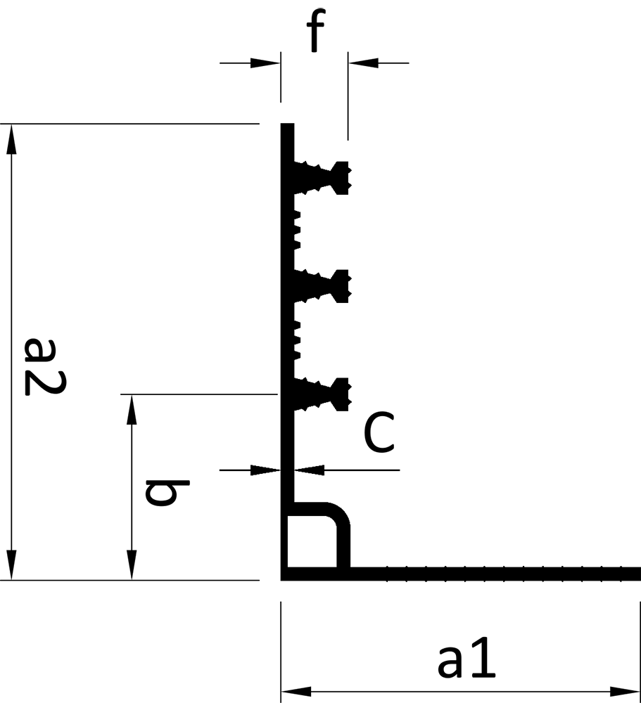
| Total width a1/a2 (mm) | Width b (mm) | Width c (mm) | Anchoring ribs N x f (mm) | Water pressure P (bar) | Resulting movement Vr (mm) |
| AM 350 Ki * | |||||
| 166/211 | 86 | 6 | 3 x 31 | 0.7 | 20 |
|
|
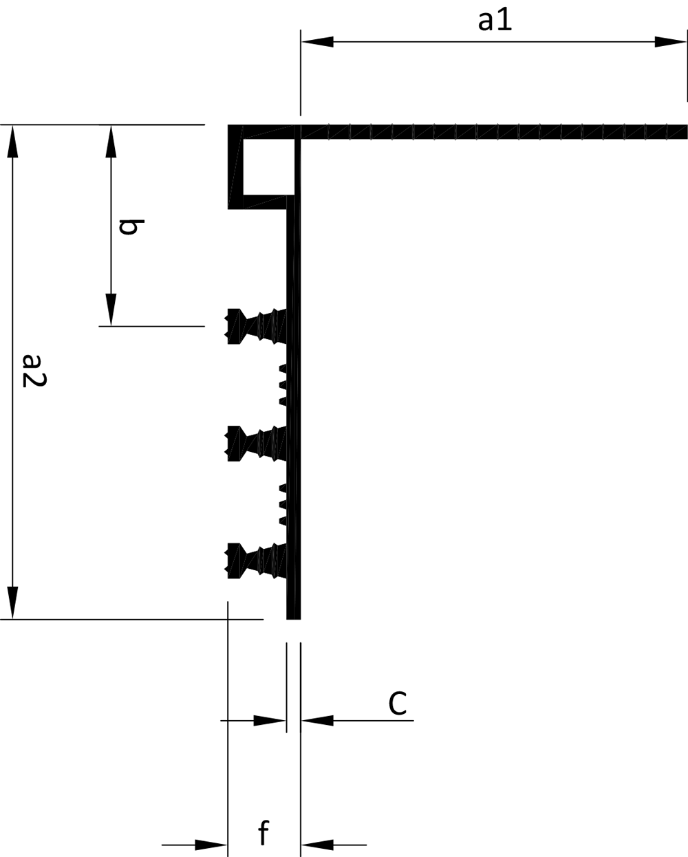
| Total width a1/a2 (mm) | Width b (mm) | Width c (mm) | Anchoring ribs N x f (mm) | Water pressure P (bar) | Resulting movement Vr (mm) |
| AM 350 KA | |||||
| 166/211 | 86 | 6 | 3 x 31 | 0.7 | 20 |
|
|
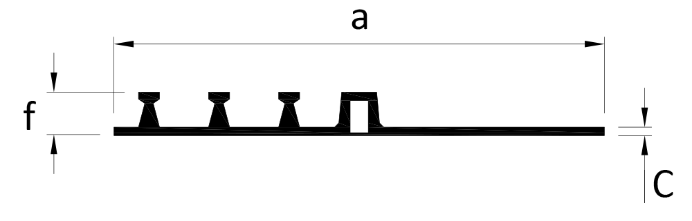
| Total width a (mm) | Width b (mm) | Width c (mm) | Width s (mm) | Water pressure P (bar) | Resulting movement Vr (mm) |
| AM 350 KF | |||||
| 350 | --- 1) | 6 | 3 x 31 | 0.7 | 20 |
| A 350 KF | |||||
| 350 | --- 1) | 6 | 3 x 31 | 0.7 | 3 2) |
|
|
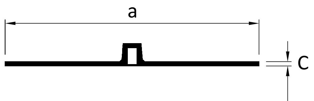
| Total width a (mm) | Width b (mm) | Width c (mm) | Width s (mm) | Water pressure P (bar) | Resulting movement Vr (mm) |
| AMG 350 | |||||
| 350 | --- 1) | 6 | 3 x 31 | 0.7 | 20 |
*Stock items
1) Dependant on installation position
2) Other data dependent on installation position
3) Clamping on the side facing water
a1= Width of clamping part including central bulb
a2 = Width of cast-in part including central bulb
vr = Resulting movement (vx² + vy² + vz²) ½
N No. of anchoring ribs
f Depth of profile (depth of anchoring ribs including base plate)
Shore A hardness
| 62 ± 5 | DIN ISO 7619-1 |
Tensile strength
| ≥ 10 MPa | DIN 53504 |
Elongation
| ≥ 380% | DIN 53504 |
Tear strength
| ≥ 8 N/mm | DIN ISO34-1: 2004-07 |